After having had the shutter button mechanism break twice, due to using a cable remote which was pulled :-(, I decided to investigate fitting a remote control.
First the pages from the Fuji S602 site were a tremendous help, initially in checking how to open the camera and then repair the broken shutter button the second time. It was then that I realised that there was sufficient room behind the LCD display to mount a remote control receiver. However finding the shutter and focus switch connections was another matter until I hit the relevant page on the above site again :-) Where Jim has already identified the ribbon cable connections!
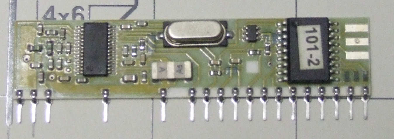
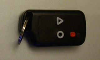
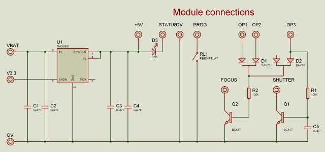
So where to start, rather than build from scratch I located an existing remote control intended for embedding in other equipment from RF Solutions the HiRK-433F was chosen accompanied by a 3 button Key Fob transmitter. Three buttons to replace two ? Well I wanted to be able to lock the half press focus button and so choose to have a shutter, focus and toggle focus switch so that the focus / white balance and exposure settings could remain locked between several shots - handy when doing Pano's of course ! However this didn't quite work out as the camera ignores the half-press condition when the shutter switch is released returning to a state which ignores the half-pressed signal until released and re-asserted thus losing the previous settings :-(
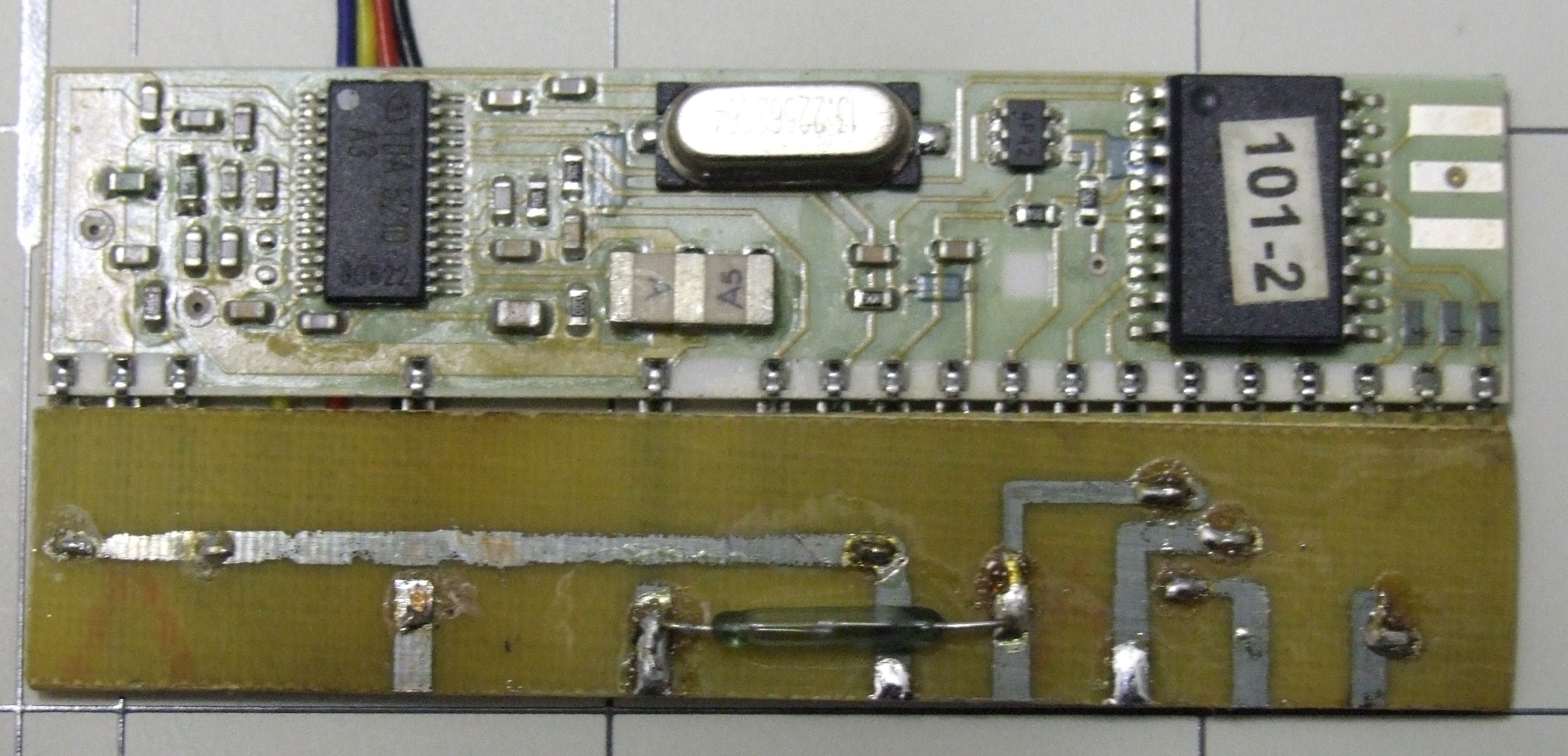
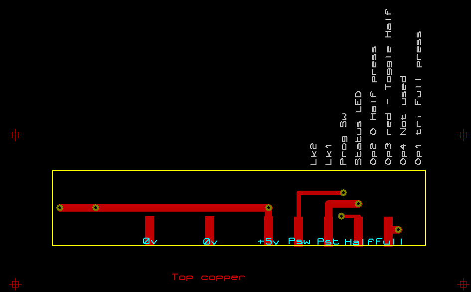
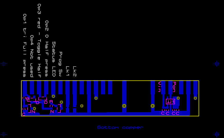
The receiver module has a mode where by two of the signals are momentary and the third one is latched - hence the choice of this module. However the three signals do need combining and a 5volt supply needs to be derived from the battery supply and controlled to minimise battery drain so there are some additional circuits that need to be added as well hence the need for a small thin PCB to which the module is fitted.
If you wish to have ago yourself you will need a sensible knowledge and experience in electronics and SMD technology, this isn't a "kit" design by any means!!!! Below in pictures is sufficient information if you have the relevant knowledge :-)
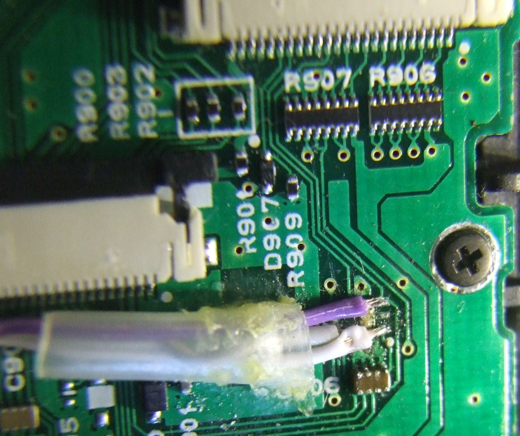
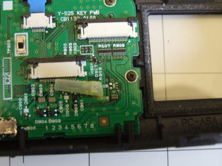 Rear case with KEY Printed Wiring Boards
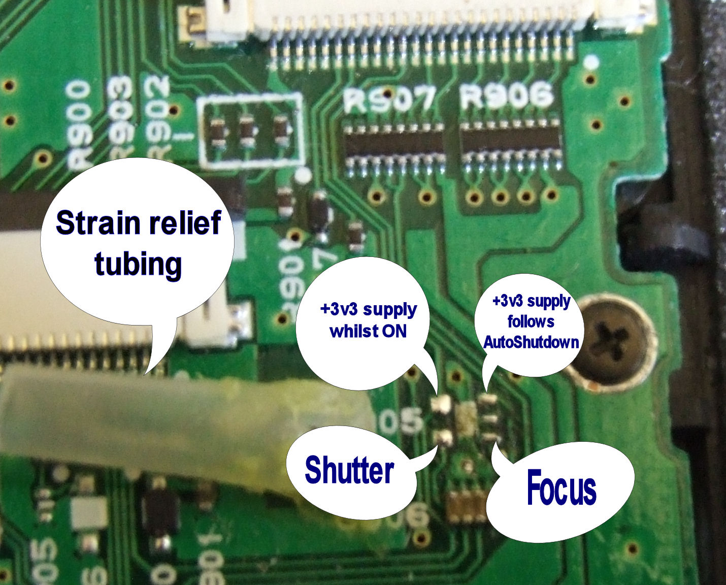
Close up of connections - these are based on a SOT23-5 set of pads for some reason but have all the signals needed for this modification!!! How lucky!
The +3.3v signal that follows the auto shut down signal is used to control the +5volt regulator powering the receiver module thus ensuring that minimum drain is placed on the batteries.